Monthly Archives: March 2026

Designing Reliable RF Communication Systems for Harsh Environments

Designing Reliable RF Communication Systems for Harsh Environments

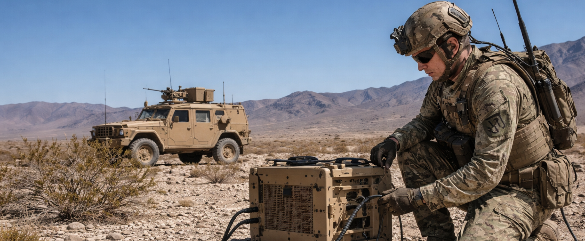
Military and defense RF systems are rarely deployed in ideal conditions. From desert heat to arctic cold, airborne vibration to underground humidity, harsh environments introduce performance risks that can quickly degrade signal integrity and system reliability. Designing for these realities requires a deliberate approach to architecture, protection, and long-term stability.

Environmental Stressors and Their Impact on RF Performance

Extreme conditions directly affect RF behavior at both the component and system level:

  • Temperature fluctuations can shift frequency stability, increase insertion loss, and reduce amplifier efficiency.
  • Vibration and shock (common in vehicles, aircraft, and naval platforms) can loosen connectors, damage cables, and degrade alignment.
  • Moisture, dust, and salt exposure introduce corrosion, impedance mismatch, and signal attenuation.
  • Electromagnetic interference (EMI) in dense operational environments can reduce signal-to-noise ratio (SNR) and overall link reliability.

In traditional coaxial-based systems, these effects compound over distance, increasing loss and requiring amplification often adding more points of failure.

Designing for Reliability in the Field

To ensure consistent performance, RF systems must be engineered with resilience in mind:

  • Component Selection: military-grade connectors, sealed enclosures, and temperature-rated materials help prevent early failure.
  • Redundancy Planning: critical links should include failover paths to maintain uptime during component degradation.
  • Environmental Sealing: IP-rated housings and proper cable shielding protect against moisture and particulate ingress.
  • Thermal Management: passive and active cooling strategies maintain stable operating conditions across wide temperature ranges.

Reliability is not just about surviving the environment. It’s about maintaining predictable RF performance despite it.

Extending Performance with RF over Fiber

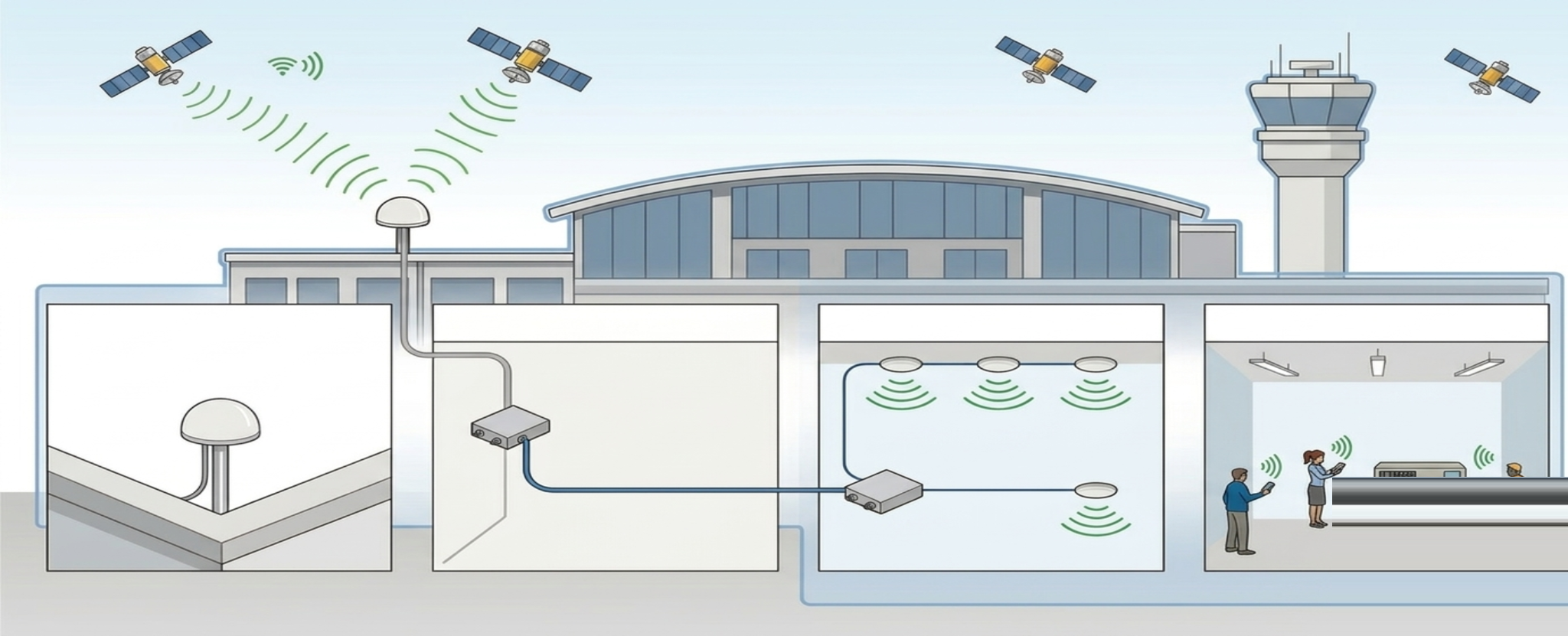
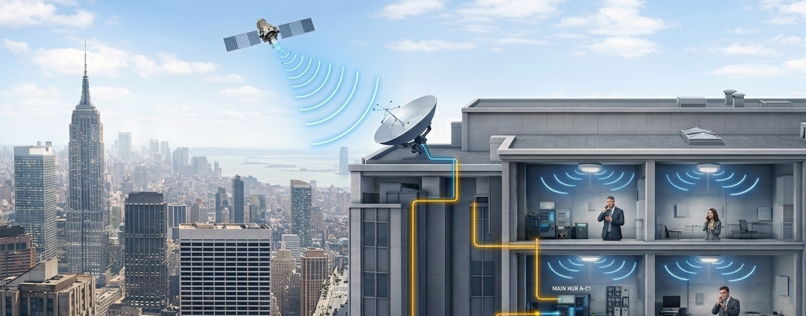
One of the most effective strategies for mitigating environmental impact is the adoption of RF over Fiber (RFOF) architectures.

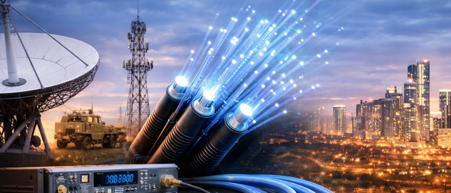
Unlike coaxial cables, fiber is immune to electromagnetic interference, significantly reduces signal loss over long distances, and is not susceptible to corrosion or grounding issues. This makes rf over fiber solutions particularly valuable in distributed and remote military deployments.

Key advantages of rfof applications in harsh environments include:

  • Low-loss transmission over extended distances without the need for multiple amplifiers
  • Immunity to EMI and lightning effects, critical in exposed or high-interference zones
  • Lightweight and flexible cabling, reducing mechanical stress under vibration
  • Improved system isolation, enhancing overall signal integrity

Modern rf over fiber products are designed with ruggedized enclosures and military-grade specifications, enabling deployment across air, land, and sea platforms.

Planning Considerations for Harsh Deployments

When designing RF systems for defense environments, planners and engineers should consider:

  • Link budget margins that account for environmental degradation over time
  • Installation constraints, including routing through confined or exposed areas
  • Maintenance accessibility, especially in remote or hazardous locations
  • Scalability, ensuring systems can adapt to evolving mission requirements

Integrating rf over fiber early in the design phase allows for more flexible architectures and reduces long-term operational complexity.

Building for Long-Term Stability

Harsh environments don’t just test systems at deployment. They continuously challenge them over their lifecycle. Materials degrade, connections loosen, and performance drifts.

Designing for long-term stability means minimizing failure points, reducing maintenance needs, and ensuring consistent RF performance under all conditions. Technologies like RFOF play a central role in achieving this by simplifying infrastructure while enhancing resilience.

Ultimately, reliable RF communication in defense applications is not just about initial performance. It’s about sustained, predictable operation when it matters most.

Frequently Ask Questions (FAQs)


How do extreme temperatures affect RF systems?
Temperature changes can alter component characteristics, leading to frequency drift, increased loss, and reduced amplifier efficiency. Proper thermal design and component selection are critical.

Why is vibration a major concern in military RF deployments?
Vibration can physically damage connectors and cables, causing intermittent failures or signal degradation. Ruggedized components and secure mounting are essential.

How does RF over Fiber improve reliability in harsh environments?
RF over Fiber eliminates many traditional failure points by reducing reliance on long coaxial runs, minimizing signal loss, and providing immunity to EMI and environmental corrosion.

Are RF over Fiber systems suitable for all military applications?
Most RFOF applications including airborne, naval, and ground-based systems benefit from fiber-based transport, especially where distance, interference, or environmental exposure are concerns.

What should engineers prioritize for long-term system stability?
They should focus on durable materials, simplified architectures, environmental protection, and technologies like rf over fiber solutions that reduce maintenance and performance variability over time.

Do RF over Fiber products require special maintenance?
Generally, rf over fiber products require less maintenance than coax-based systems due to fewer active components and reduced susceptibility to environmental damage.


How GPS Coverage is Extended Inside Buildings and Enclosed Spaces

How GPS Coverage is Extended Inside Buildings and Enclosed Spaces

Imagine a maintenance crew working inside an aircraft hangar. Outside, navigation systems lock instantly onto satellite signals. But once the aircraft is pulled indoors, GPS drops out completely. For teams relying on positioning, timing, or synchronization, that loss of signal isn’t just inconvenient it can disrupt operations.

This is a common challenge across many environments: large buildings, underground facilities, tunnels, and secure bunkers. GPS and GNSS signals are inherently weak by the time they reach Earth, and structures made of concrete, steel, or composite materials block them almost entirely. So how do you maintain continuous positioning indoors?

Bringing GPS Indoors: The Basic Idea

The solution is simpler than most people expect. Instead of trying to generate GPS signals inside a building, systems are designed to capture them outside where they are strong and extend them indoors. This is where GPS repeaters (also known as GNSS repeaters) come into play.

A typical setup works like this:

  • An outdoor antenna is placed in a location with clear sky visibility
  • It receives live GPS/GNSS satellite signals
  • These signals are then transported into the building
  • Indoor antennas rebroadcast the signal locally

The result: devices inside the structure behave as if they are still outdoors, maintaining lock on satellite signals without interruption.

Extending Coverage Without Complexity

Modern GPS signal repeater systems are designed to extend coverage cleanly and reliably, without introducing noise or distortion. One increasingly common approach uses GNSS GPS fiber solutions, where signals are transported over fiber instead of traditional coaxial cable.

Why does that matter?

  • Distance: Fiber enables signals to travel much farther without degradation
  • Signal Integrity: Maintains accurate timing and positioning data
  • Flexibility: Ideal for large or complex environments like campuses or multi-level facilities

This makes solutions, such as an indoor GPS repeater or a GPS repeater for hangar, particularly effective in scenarios where coverage must span long distances or multiple zones.

Where Indoor GPS Coverage Matters

Extending indoor GPS coverage isn’t just a technical upgrade. It enables real operational continuity. Common use cases include:

  • Aircraft hangars: Supporting navigation system testing and maintenance
  • Military and defense sites: Ensuring GPS availability in secure or underground locations
  • Warehouses and logistics hubs: Enabling asset tracking and automation
  • Research labs and testing facilities: Providing controlled GNSS environments

In all of these cases, the goal is the same: seamless transition between outdoor and indoor environments, with no loss of signal or performance.

Why Continuity Is Critical

Many systems today rely on uninterrupted GPS not just for positioning, but for timing synchronization and operational coordination. When a signal drops, it can affect:

  • Equipment calibration
  • Network synchronization
  • Safety systems
  • Testing accuracy

By using a GPS repeater, organizations ensure that GPS-dependent systems continue to function exactly as expected, regardless of location.

Maintaining GPS access shouldn’t stop at the building entrance. With the right approach, organizations can extend reliable satellite coverage indoors, ensuring continuity, accuracy, and performance wherever it’s needed.

Frequently Asked Questions (FAQs)


Can GPS work inside buildings without assistance?

Generally, No. GPS signals are too weak to penetrate most building materials effectively, especially in dense or enclosed environments.

What is a GPS repeater?
A GPS signal repeater captures live satellite signals outdoors and retransmits them indoors, enabling GPS-enabled devices to function inside buildings.

Is there a difference between GPS and GNSS repeaters?
Yes. GPS refers specifically to the U.S. system, while GNSS includes multiple global systems (like Galileo or GLONASS). GNSS repeaters can handle multiple constellations.

How is signal quality maintained indoors?
High-quality systems especially those using gnss gps fiber solutions preserve signal integrity over long distances, ensuring accurate positioning and timing.

Can I use a GPS repeater in a hangar or underground facility?
Yes. Solutions like a GPS repeater for hangar are specifically designed for large, enclosed spaces and can extend coverage effectively even below ground.

Do indoor GPS repeaters require complex installation?
Not necessarily. Most systems are modular and designed for straightforward deployment, with scalability depending on the size and layout of the facility.

Why Satellite Phones Stop Working Indoors – And How Repeaters Solve the Problem

Why Satellite Phones Stop Working Indoors – And How Repeaters Solve the Problem

Satellite phones and GNSS receivers are engineered for open-sky operation. They rely on a direct line-of-sight to orbiting satellites to function correctly. But real-world environments rarely cooperate. Control rooms, underground bunkers, aircraft hangars, and dense buildings all introduce one critical problem: they block satellite signals entirely. This is where an Iridium repeater or GNSS repeater becomes essential.

Why Satellite Signals Fail Indoors

Satellite signals are inherently weak. By the time they reach Earth, they arrive at extremely low power levels-just enough for sensitive receivers under ideal conditions.

Once those signals encounter physical barriers, performance drops quickly:

  • Concrete, steel, and reinforced structures heavily attenuate RF signals
  • Modern building materials further reduce signal penetration
  • Underground facilities and enclosed hangars eliminate sky visibility entirely

Even partial obstruction can degrade positioning accuracy or cause complete signal loss.

The Operational Impact

This limitation creates real challenges in operational environments:

  • Personnel must leave secure areas to place satellite calls
  • Emergency communication is delayed or disrupted
  • Aircraft must be moved outdoors for GNSS and avionics testing
  • GPS devices lose lock when brought indoors

In many cases, these inefficiencies directly impact safety, cost, and workflow continuity.

How Satellite Repeaters Solve It

An Iridium repeater or GNSS repeater extends satellite coverage indoors by capturing and redistributing live signals.

The architecture is simple and scalable:

  • An outdoor antenna captures satellite signals with clear sky visibility
  • The signal is transported indoors via coaxial cable or RF over fiber (RFoF) links
  • Indoor antennas rebroadcast the signal across the facility

Using RF over fiber solutions enables low-loss transport over long distances, making it ideal for large campuses, underground facilities, or distributed systems where coax alone is not sufficient.

With a properly designed RF over fiber or coax-based repeater system:

  • Satellite phones function reliably indoors
  • Aircraft navigation and GNSS systems can be tested inside hangars
  • GPS receivers maintain continuous lock-even underground
  • Operations remain fully contained within secure or controlled environments

The system creates a stable, repeatable satellite signal environment independent of physical location.

Satellite communication has always been limited by one requirement: direct visibility to the sky.

Iridium repeater and GNSS repeater systems remove that limitation-extending coverage wherever it’s needed. Combined with RF over fiber solutions, they enable high-performance satellite signal distribution across virtually any environment.

The result is simple: reliable satellite connectivity, anywhere it’s required.

What Limits Maximum Transmission Distance in Coaxial RF Networks?

What Limits Maximum Transmission Distance in Coaxial RF Networks

In any coaxial RF network – whether supporting a DAS deployment in a stadium, a satellite teleport, or a tactical communications system – maximum transmission distance is not arbitrary. It is defined by physics and quantified through three fundamentals: link budget, signal-to-noise ratio (SNR), and noise figure (NF).

Understanding how these interact reveals why distance ceilings appear sooner than many engineers expect – and why optical transport has become the long-range alternative.

1. Link Budget: Where the Distance Limit Begins

A coax link budget is straightforward:
Received Power = Transmit Power − Cable Loss − Connector/Passive Loss + Amplifier Gain
The limiting factor is cable attenuation, which increases with both frequency and distance.
Example Calculation

Assume:

  • Frequency: 2 GHz
  • Cable: 1/2″ low-loss coax (~6.5 dB per 100 m at 2 GHz)
  • Distance: 300 m
  • Connector/pasitic losses: 2 dB

Cable loss = 6.5 × 3 = 19.5 dB
Total path loss ≈ 21.5 dB

If transmit power is +10 dBm, received power becomes roughly –11.5 dBm – before considering noise.

At L-band (1–2 GHz) in teleports, C-band IF transport, or cellular DAS backhaul, those losses accumulate quickly. At higher microwave frequencies, they accelerate dramatically.

2. SNR: The Real Distance Governor

Signal strength alone does not define usable distance. The real constraint is maintaining adequate SNR at the receiver.

Thermal noise floor (at 290K):
–174 dBm/Hz

For a 20 MHz channel:
Noise power ≈ –174 + 73 = –101 dBm

If the receiver requires 15 dB SNR, minimum signal level must exceed –86 dBm.

As coax length increases, signal drops – but noise introduced by amplifiers and active devices does not decrease.Once SNR crosses below system requirements, performance collapses.

This is particularly critical in:

  • Large DAS systems with multiple remote nodes
  • Satellite teleports transporting L-band IF across antenna farms
  • Tactical systems where long temporary cable runs are unavoidable

3. Noise Figure and Amplifier Cascades

To extend coax distance, engineers insert inline amplifiers. But amplification introduces its own penalty: cumulative noise figure.

Using Friis’ Formula:
NF_total = NF₁ + (NF₂ – 1)/G₁ + (NF₃ – 1)/(G₁G₂) …

Each added amplifier:

  • Raises system noise
  • Increases distortion risk
  • Consumes power
  • Adds failure points
  • Requires environmental protection (especially outdoors)

After several cascaded stages, improving gain no longer improves SNR meaningfully – it simply amplifies noise along with the signal.

This is the practical ceiling in large coaxial infrastructures.

4. Typical Distance Comparison

Below is a simplified comparison at ~2 GHz using high-quality coax:

Architecture | Practical Distance | Amplifiers Required | Noise Impact
Passive Coax | 100–200 m | None | Minimal
Coax + 1 Amp | 300–500 m | 1 | Moderate
Coax + Multi Amp Cascade | 500–1000 m | 2–4 | Significant cumulative NF
Optical (RFOF) | 10–40+ km | None (inline) | Negligible added RF noise

The contrast is clear: coax scales linearly in loss, but amplifier-based extension scales exponentially in complexity.

5. Why Optical Transport Changes the Equation

This is where rf over fiber architectures fundamentally shift design limits.

In an rfof link:

  • RF is converted to optical
  • Transport occurs over fiber with ~0.2–0.4 dB/km loss
  • No intermediate RF amplification is required
  • No cumulative noise figure stacking occurs in the RF domain

Instead of managing gain stages and SNR recovery every few hundred meters, engineers can span tens of kilometers cleanly.

Modern rf over fiber solutions are widely deployed in:

  • Large-scale DAS networks
  • Satellite teleport antenna farms
  • Defense and tactical communications infrastructure
  • Broadcast and remote radio head deployments

These rfof applications eliminate coaxial distance constraints while simplifying infrastructure design.

Additionally, compact and ruggedized rf over fiber products are now available for field and mobile use, making optical transport viable beyond fixed facilities.

Maximum transmission distance in coaxial RF networks is governed by:

  • Attenuation (link budget limits)
  • SNR requirements
  • Cumulative noise figure from amplifier cascades

Beyond a few hundred meters at GHz frequencies, maintaining performance requires increasing amplification complexity – with diminishing returns.

Optical transport avoids this trade-off. By removing inline RF gain stages and dramatically reducing transmission loss, rf over fiber solutions extend range from hundreds of meters to tens of kilometers – without stacking noise penalties.

For modern DAS, teleport, and tactical architectures, the question is no longer how far coax can go – but whether coax is the right medium at all.

Key Considerations When Upgrading RF Transport Systems with Fiber Optics

Key Considerations When Upgrading RF Transport Systems with Fiber Optics

Provide a practical checklist covering distance requirements, frequency range, scalability, and integration with existing equipment for fiber-based, RF-transport solutions.

Upgrading an RF transport system isn’t just a component replacement it’s a strategic infrastructure decision. Whether you’re working in telecom, satellite communications, defense, or broadcast, the right upgrade should improve signal integrity today while preparing your network for tomorrow’s demands.

Here’s a practical engineering checklist to guide the process and determine when fiber-based transport makes the most sense.

1. Distance Requirements

Copper works well over short runs. But as distance increases, especially at higher frequencies, attenuation becomes significant, often requiring amplification that adds noise and complexity.

If your upgrade involves remote antennas, distributed equipment rooms, or campus-wide deployments,  rf over fiber technology enables RF signals to be transported over kilometers with minimal loss and no EMI concerns.

Longer distances are often the first indicator that fiber-based transport should be considered.

2. Frequency Range & Bandwidth

An upgrade should account for both current and future spectrum needs.

Key questions:

  • What frequency bands must be supported today?
  • Are higher frequencies planned?
  • Will bandwidth requirements expand?
  • Is multi-band support required?

Higher frequencies are more vulnerable to loss over coax. Modern rfof systems maintain wideband linear performance across broad frequency ranges, making them well suited for evolving, multi-service environments.

When evaluating rf over fiber products, verify:

  • Frequency coverage
  • Linearity and dynamic range
  • Noise figure
  • Phase stability

Designing for growth avoids costly redesign later.

3. Scalability

Many RF systems expand over time more antennas, more sectors, more bands, or redundancy requirements.

Copper infrastructures can quickly become bulky and difficult to manage. In contrast, modular rf over fiber solutions enable incremental expansion without overhauling the entire cable plant.

If growth is part of your roadmap, scalability should heavily influence your upgrade decision.

4. Integration with Existing Equipment

Any new transport system must work seamlessly with your current RF chain.

Consider:

  • Compatibility with legacy equipment
  • Connector and impedance standards
  • Power availability at remote sites
  • Monitoring and management requirements

One of the advantages of rfof applications is signal transparency. Optical RF links act as analog extensions of the original signal, typically requiring minimal changes to existing equipment.

5. EMI, SWaP & Environment

Dense RF environments, such as data centers, military platforms, urban telecom sites, increase the risk of electromagnetic interference. Copper cables can radiate and absorb noise. Fiber is immune to EMI and provides inherent electrical isolation.

Fiber also offers advantages in size, weight, and routing flexibility, which are critical in aerospace, defense, and retrofit deployments.

6. Total Cost of Ownership

Upgrades shouldn’t be judged on hardware cost alone.

Evaluate:

  • Installation complexity
  • Signal conditioning requirements
  • Maintenance and troubleshooting
  • Expansion costs
  • Downtime risk

While fiber may have a higher upfront component cost, reduced loss, fewer amplifiers, easier scalability, and improved reliability often lower long-term operational expenses.

When Fiber Becomes the Logical Upgrade

If your system upgrade involves:

  • Long-distance RF transport
  • High-frequency or multi-band operation
  • EMI-sensitive environments
  • Distributed architectures
  • Planned expansion

Then rf over fiber solutions are often the most future-ready choice.

Today’s rf over fiber products are engineered for high linearity, stability, and reliability, delivering performance that traditional copper transport increasingly struggles to match.

Upgrading RF transport is an opportunity to modernize infrastructure, simplify expansion, and protect signal integrity. By evaluating distance, frequency range, scalability, integration, and long-term cost, engineers can move beyond incremental fixes and implement an architecture built for the next generation of RF demands. In many modern deployments, that architecture is fiber-based.