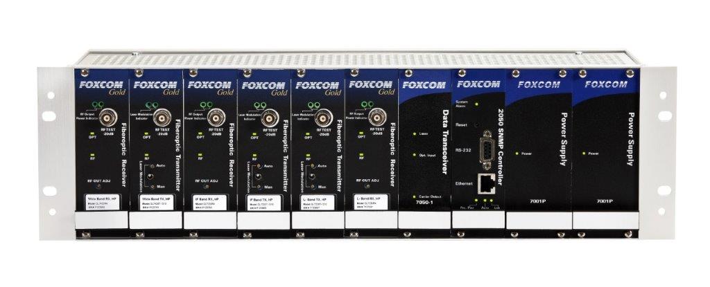
1:1 Redundant Switch | Model 2040
The Model 2040 provides 1:1 redundant switching for Sat-Light TM Interfacility Link products, including the IF and L-Band product lines. The Model 2040 supercedes the Model 2000 Switch and is backward compatible, integrating into existing systems. The Model 2040’s many features allow the operator to configure the product to meet demanding system requirements.
The Model 2040 can be controlled either locally or remotely. Global Foxcom’s Apogee SNMP Management system set the switching state (remote/local) or transmission path (A/B). However, in the case of a fault in the SNMP manager, the user can override the SNMP manager and return to control locally via the front panel “override” switch.
The Apogee manager graphically displays the active path. By activating a pin in the unit’s interface 9-pin connector, the system operator can eeasily switch between Local and Remote control. Switching from the primary to redundant path can be performed by the Model 2040 manually or automatically. Note that when the unit switches to the redundant channel, it will lock and continue to transmit over that channel regardless of the input to the primary channel. The high reliabilty, high-frequency relay redundancy switch can be configured to detect faults in the RF signal, the optical signal, or both. In addition the user can set the threshold level at which the 2040 switch detects loss of RF signals.
The Model 2040 provides two methods to detect which channel is operating: 1/ Via a 3-pin Molex connector on the rear panel; 2/ Through the chassis via the 9-pin connector.
Redundant paths are configured using an RF splitter (Global Foxcom P/N 2X012) which transmits the RF signal to two Sat-Light transmitter modules. These modules are connected via singlemode fiberoptic cable to two Sat-Light receivers. Each receiver module connects to the Model 2040 via a supplied coaxial jumper cable. The Model 2040 then transmits the RF output signal to the end device.
Features & Benefits
- Automatic or Manual Switching
- Remote operation possible via SNMP manager
- Local Override switch
- DC to 2.9 GHz bandwith
- Rapid Switching to allow signal continuity
- Adjustable signal level detection
- Locking switch circuit
Basic Details
The Model 2040 provides 1:1 redundant switching for Sat-Light TM Interfacility Link products, including the IF and L-Band product lines. The Model 2040 supercedes the Model 2000 Switch and is backward compatible, integrating into existing systems. The Model 2040’s many features allow the operator to configure the product to meet demanding system requirements.
The Model 2040 can be controlled either locally or remotely. Global Foxcom’s Apogee SNMP Management system set the switching state (remote/local) or transmission path (A/B). However, in the case of a fault in the SNMP manager, the user can override the SNMP manager and return to control locally via the front panel “override” switch.
The Apogee manager graphically displays the active path. By activating a pin in the unit’s interface 9-pin connector, the system operator can eeasily switch between Local and Remote control. Switching from the primary to redundant path can be performed by the Model 2040 manually or automatically. Note that when the unit switches to the redundant channel, it will lock and continue to transmit over that channel regardless of the input to the primary channel. The high reliabilty, high-frequency relay redundancy switch can be configured to detect faults in the RF signal, the optical signal, or both. In addition the user can set the threshold level at which the 2040 switch detects loss of RF signals.
The Model 2040 provides two methods to detect which channel is operating: 1/ Via a 3-pin Molex connector on the rear panel; 2/ Through the chassis via the 9-pin connector.
Redundant paths are configured using an RF splitter (Global Foxcom P/N 2X012) which transmits the RF signal to two Sat-Light transmitter modules. These modules are connected via singlemode fiberoptic cable to two Sat-Light receivers. Each receiver module connects to the Model 2040 via a supplied coaxial jumper cable. The Model 2040 then transmits the RF output signal to the end device.
Basic Details
| RF Specification | Value |
| Frequency Range – Bandwidth | DC – 950 MHz; 950 – 2400 MHz; 2400 – 2900 MHz |