
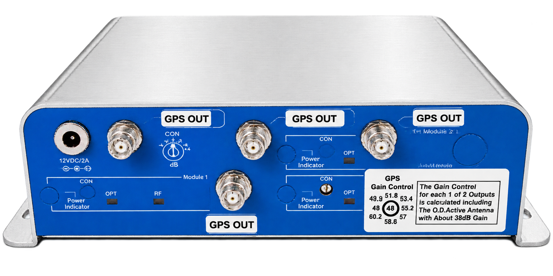
Compact GNSS Optical Link Receiver – Quad RF Outputs
Global Foxcom’s Compact GNSS Optical Link Receiver converts one fiber-delivered GNSS signal into four RF outputs for direct connection to multiple GPS or GNSS receiver antenna ports. The compact module creates a centralized distribution point for navigation, timing and reference equipment located away from the outdoor antenna. Its quad-output architecture reduces the need for separate optical receivers and individual fiber links for each connected device.
Features & Benefits
- One optical input distributes GNSS signals through four RF outputs
- Direct connection to up to four GPS or GNSS receiver antenna ports
- Centralized signal distribution
- Supports GPS, Galileo, GLONASS and BeiDou services
- 1100–1600 MHz RF frequency range
- Variable RF gain up to 44 dB for equipment-level signal adjustment
- Up to 3 dB optical budget
- Supports single-mode fiber transmission up to 6 km
- 1310–1550 nm optical operating wavelength
- SC/APC optical input and four SMA female RF outputs
- Compact 208 × 138 × 50 mm enclosure
- 12 VDC operation with power consumption below 5 W
- Supplied with a 100–220 VAC, 50/60 Hz AC-to-DC power adapter
- Standard 5-year warranty
This quad-output optical receiver is designed for direct GNSS connection applications where GPS or GNSS receiver equipment requires access to a remote antenna source. It receives the optical GNSS signal through the SC-APC fiber input, converts it back into RF, and distributes the recovered signal through four SMA (F) RF outputs for connection with compatible receiver antenna ports. Supporting GPS L1/L2/L5, Galileo E1/E2/E5a+b, GLONASS G1/G2/G5, and BeiDou B1/B2 services, it provides a centralized interface for multiple GNSS equipment connections.
The optical link architecture supports antenna-to-equipment separation of up to 6km through fiber transmission. With a 1100–1600MHz RF frequency range, variable RF gain up to 44db, and up to 3db optical budget, this receiver supports RF level configuration based on connected equipment requirements. Its compact 208 × 138 × 50mm enclosure, 12VDC operation, and SC-APC optical interface support integration into navigation, timing, and reference equipment installations. Compatible remote antenna options can be selected from the GNSS Antennas category.
| RF | |
| GPS Support | GPS L1, L2, L5, Galileo E1, E2, E5a+b, GLONASS G1, G2, G5, and BeiDou B1/B2 |
| Frequency Range | 1100 to 1600MHz |
| RF Gain | Variable |
| GPS RF Gain Range | Up to 44dB |
| RF Output Connector | SMA (F) |
| Optical | |
| Operating Wavelength | 1310 to 1550nm |
| Optical Budget / Fiber Length | Up to 3dB (6Km of fiber) |
| Optical Connector Type | SC-APC |
| Mechanical & Electrical | |
| Operating Voltage | 12VDC |
| Power Consumption | <5Watt |
| Unit Size | 208x138x50mm |
How does the Quad RF Output Optical Link Receiver support multiple GNSS equipment connections?
The receiver converts the fiber-delivered GNSS signal back into RF and provides four SMA RF outputs for connection with compatible GPS and GNSS receiver antenna ports. This enables multiple devices to share the same remote GNSS antenna source through a single optical link.
What type of GNSS equipment can connect to the RF outputs?
The RF outputs are designed for direct connection to compatible GPS and GNSS receiver antenna ports. Applications may include navigation, synchronization, timing, and reference equipment operating within the supported GNSS frequency range.
Do the four RF outputs provide separate GNSS sources?
The four RF outputs distribute the GNSS signal recovered from the single optical input. Each output provides a separate physical connection for connected receiver equipment, while all outputs originate from the same incoming GNSS signal source.
Which GNSS services and frequency bands are supported by this receiver?
The receiver supports GPS L1, L2, L5, Galileo E1, E2, E5a+b, GLONASS G1, G2, G5, and BeiDou B1/B2 signals through the optical GNSS link.
How does adjustable RF gain support integration with connected equipment?
The variable RF gain, with GPS RF gain range up to 44db, enables adjustment of the recovered RF signal level according to connected equipment requirements. The configured level should consider fiber loss, RF cable attenuation, and the input specifications of the connected GNSS receiver.
What fiber distance can be supported between the GNSS antenna location and receiver equipment?
The receiver supports fiber transmission up to 6km with an optical budget of up to 3db. The achievable distance depends on the total optical loss introduced by the installed fiber path, connectors, and other optical components.
What optical and RF interfaces are used for system integration?
The receiver uses an SC-APC optical input for fiber connection and four SMA (F) RF outputs for connection to compatible GNSS receiver antenna ports.